MANUAL
We are still working in the manual, please be patient.
Index
Quick start guide (^ back to index)
Extensible Input Manager bundles in one package: the posibility of defining your own devices, graphical input manager table, handheld virtual and accelerometer joysticks and a runtime customizable control options menu. Many more small features are included also: for example multitouch emulator allows you to test your handheld games inside the editor.
You can use both gui tables and/or scripting to operate with the library.
In addition this extension includes all the source code, so you can customize and change it (we recomend to extend classes instead of changing the provided code itself because newer releases may overwrite your customized code).
First steps (^ back to index)
There are two ways of using this library: gui or coding.
For use gui mode, first attach a instance of GInputManager to a GameObject in your scene. This will provide you with a table like the Unity Input Manager.
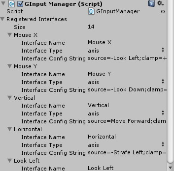
By default, even if the table is empty, you will have already defined the unity input manager axes and buttons. Now, using this table you can define new axes or buttons or overwrite the configuration for the unity input manager defined ones.
Each axis/button in extensible input manager should be binded to an interface type, which is a inteface device driver that manages that entry. You can also specify a configuration for the interface, which will make that driver make one thing or other.
You can use the provided drivers, define your own interface drivers or use extensions provided by third party developers. In case of that the driver is not registered in the interface type dropdown, simply select Custom and write in the configuration type=YourDriverName; and it will start to work. You can also bind to one of the 16 user entries, provided for ease, by making one of the 16 classes to inherit from yours. That was the legacy way.
Once the driver interface type is binded, the default configuration will appear in the Interface Config String field. You can change it or add new fields. Each driver has it's own configuration, so you must consult the documentation regarding the driver you are using.
On the other hand you can use code for initialize the library. This is the only way posible in the free bundle, as it is only for testing one or two drivers. For production purposes use best computer or handheld production libraries.
For initialize the library with code you don't need to do nothing: by default the library starts itself the first time is used, even if you don't register any axis or button, library will use the unity input manager defined ones.
You can, as with the input manager table, define your own axes/buttons or overwrite the ones defined in the unity input manager.
For doing so, you simply need to register a new interface by using:
GInput.registerInterface("YourAxisOrButtonName", new InterfaceDriverClass());
GInput.configInterface("YourAxisOrButtonName", "config string");
Where YourAxisOrButtonName is the name of the interface, you can name it Horizontal or Vertical to overwrite the Unity defaults.
InterfaceDriverClass is the name of the class implementing the interface driver module, it can be one of the provided, for example: GInputInterfaceAxis or GInputMultiTouchX.
It can be also a class developed by yourself, implementing the GInputInterface, or a class developed by a third party.
Finally after running registerInterface you can run optionally configInterface to configure the interface. Use as first parameter the same name used before in the registerInterface.
As second parameter write a configuration string, this is the same string that you write in the input manager object table in the gui method.
Using the library and adapting scripts (^ back to index)
You can perform this step even without making the First Steps, but it is better if you already redefined or defined some new axes.
Once defined, this library behaves EXACTLY as the standard input manager and input object interfaces.
You can write this header line in your files:
using Input = com.gargore.InputManager.Override.Input;
and after that Input object will be managed by extensible input manager, so no further changes are needed in your code. Any code prepared to work with Unity Input system will still working and you can redefine or create special axes.
As side effect you can now use handheld multitouch joysticks as if it where standard physical devices: using Input.GetAxis and Input.GetButton.
You can use also you own non-standard devices and joysticks as if it where standard by only writing a simple driver. For example:
public class VirtualInterfaceExample: GInputInterfaceBase, GInputInterface {

  [...]

  private string configString = "";

  private string arg1 = "your internal axis name"; // default value

  private int arg2 = 1; // default value

  private bool debug = false;


  new public bool implementsInputConfig(string inputName) {

    return true;

  }


  new public string InputConfig(string inputName, string newConfigString) {

    if (newConfigString != null) {

      arg1 = GInputHelper.configGetValueString(newConfigString, "source", arg1);

      arg2 = GInputHelper.configGetValueInt(newConfigString, "arg2", arg2);

      configString = newConfigString;

    }

    return configString;

  }

  [...]

  new public float GetAxis(string inputName) {

    return YourLibrary.YourGetValueMethod(arg1, arg2);

  }

  [...]

}
Using the ingame provided menu (^ back to index)
We provide you an example ingame menu using the infrastructure for your convenience.
For using the resource, simply add a GInputMenu instance to an empty gameobject at (0,0,0) position. This will make the menu to render.
To populate the menu, in the Input Manager table, or with configInterface, write the property showinmenu, for example:
GInput.configInterface("YourAxisOrButtonName", "other;properties;showinmenu");
You can use also example1 as reference.
Using the devices (^ back to index)
Extensible Input Manager relays on the different interface virtual device drivers to work. Each one has its own configuration variables.
Configuring a device in the Input Manager table or with the configInterface method use exactly the same strings, which are processed by the different modules.
Some devices will reformat the string so you can see the default values and change it more easily. This depends on the driver implementation.
Provided device configuration (^ back to index)
Free version devices (^ back to index)
The free version provide only a example device: GInputInterfaceExample.
GInputInterfaceExample configuration (^ back to index)
GInputInterfaceExample reads the value from one Unity Input Manager axis and passes it to the caller.
Config string can have two variables: source which specifies the name of the Unity axis or button and debug, whose value can be true or false and if true makes the driver to log the value readed on each request.
For example you can specify:
GInput.configInterface("Vertical", "source=Horizontal;debug=true");
That will make Vertical axis return the horizontal values.
This driver is only a example, so no more options are available. The idea is that you use this code as reference in order to create your own drivers.
Bundle PC devices (^ back to index)
Includes in addition to the free version devices, the following ones: GInputInterfaceAxis, GInputInterfaceButton, GInputInterfacePointerX and GInputInterfacePointerY. It also provide user slots in order to bind third party or your own drivers in the input manager table.
GInputInterfaceAxis (^ back to index)
This driver is targeted to create and mix other axes.
Configuration string can have following variables:
- source, source1, source2 and/or source3: this driver can mix up to three other axes. Specify each one of the three channels (1, 2 or 3) by using source/source1 for channel 1, source2 for channel 2 and source3 for channel 3. Those channels will be mixed (usually added) and an output value will be generated. The value is a name of an axis that will be readed thru the Extensible Input Manager GetAxis method. If you want to read the value from other source you can prefix the name with unity: and key: prefixes, the ginput: corresponds to the default behaviour. Finally you can multiply the axis or invert its sign by using - or number* or -number* between the prefix and the axisname or before the axisname if no prefix is provided. For example: source=-5*Horizontal or source=unity:2*Horizontal are valid syntax values.
- clamp, clamp1, clamp2 and/or clamp3: input clamping mode. Currently you can clamp to positive or negative values, or remain unclamped. Specify -1 to clamp to only negative values: so only positive values will be replaced by 0, or +1 to clamp to positive values, if you don't specify nothing or if you specify 0 input values will be no clamped.
- absolute=true|false: you can specify true and then the value returned by the axis will be accumulated in the absolute value, instead of returning the delta -1..1 value.
- filter=0.0..1.0: you can specify a filter coefficient from 0.0 to 1.0. Values near 0.0 will make the output value from this axis to move smoother and slower and near 1.0 will make it to be unfiltered.
- min and max: you can clamp the output to two values, for example -1 and 1. By default no output clamping is performed.
- flags: this driver allow to specify flags, but currently no flag will be processed, but you can still write flags that will be processed by other parts, for example flag=menu will make the interface to be configurable by the control configuration menu provided in the library.
GInputInterfaceButton (^ back to index)
This driver allows you to use other buttons (or axis) and read them mixed like a boolean button.
Configuration string can have following variables:
- source, source1, source2 and/or source3: this driver can mix up to three other buttons. Specify each one of the three channels (1, 2 or 3) by using source/source1 for channel 1, source2 for channel 2 and source3 for channel 3. Those channels will be mixed (usually ored) and an output value will be generated and send to the invoker. The value is a name of an axis that will be readed thru the Extensible Input Manager GetAxis method. If you want to read the value from other source you can prefix the name with unity: and key: prefixes, the ginput: corresponds to the default behaviour. Finally you can specify other prefix for this driver. The touch: prefix will read if the touch axis specified is being held or not. Touch driver provide an area of the screen to make a virtual joystick, if you want to know if the area is being pressed, use this prefix.
- flags: this driver allow to specify flags, but currently no flag will be processed, but you can still write flags that will be processed by other parts, for example flag=menu will make the interface to be configurable by the control configuration menu provided in the library.
GInputInterfacePointerX and GInputInterfacePointerY (^ back to index)
Pointers are the simpler type of touch implemented. Them use only monotouch devices like mouses and allows you to define an area of the screen where the pointer can click, drag and slide or perform other actions.
Two separate drivers are provided to get the X and the Y axes corresponding to a pointer handler.
Configuration string can have following variables:
- mode: this is the most important variable. Using this variable you have three different type of devices. mode=0 is the one used for virtual joysticks (while pressed axis will displace from the point inside the area where the user started to click), mode=1 is the one used for drag&drop source (the axis will only show delta movements) and mode=2 is absolute: the neutral point is the center of the area.
- trigger: is the trigger mode: trigger=0 is the default mode, pointer will be enabled while mouse is pressed, trigger=1 is the always enabled mode: the axis will follow the pointer position even if no mouse button is pressed and trigger=2 is the toggle mode: the area will be enabled on one click and will be disable on nextone, and this repeats again.
- enabled: initial status, usually to be used with trigger=2.
- key: is the key which handlees the trigger condition, usually is "mouse 0".
- keydelay: is the time in which the library holds the key changes in order to optimize call counts. Usually is 0.3 which is the human-interactive response delay.
- priority: when various areas overlap, this determines which pointer area prevails..
- xmin, xmax, ymin, ymax: allows to determine the area on where the pointer will work in the screen. Them are relative values between 0.0 and 1.0, being 0.0 the left-bottom sides of the screen and 1.0 the right-up sides of the screen..
- flags: this driver allow to specify flags, but currently no flag will be processed, but you can still write flags that will be processed by other parts, for example flag=menu will make the interface to be configurable by the control configuration menu provided in the library.
User slots (^ back to index)
Please consult the documentation of the third party binded drivers, as user slots do nothing without a binded driver.
Bundle Handheld devices (^ back to index)
Includes the devices provided in the free library and in the computer bundle, plus following: acceleration, multitouch, and will include location, gyro and compass.
Acceleration (accelerationx, accelerationy and accelerationz) (^ back to index)
Creates a virtualized accelerometer driven joystick. It has the following configuration parameters:
- mode: the modes indicate the way of the accelerometer clamping is handed: mode=0 following clamp area: if you move beyond the clamping area, the area follows you: this is the more natural and the default style, mode=1 is the lowpass center area: the area follows the user position very slowly. This mode have the problem that after remaning quiet a while, the joystick will autocenter, but is a bit more best-responsive than the mode=0. The mode=2 is the fixed center area: you must specify the accelerometer angle area manually. This mode is not recomended.
- center: is the center position, usually important only in mode=2.
- span: is the extension of the clamping area, usually a value between 0.0 and 1.0, default value is 0.25.
- threshold: is an area outside of the span where the center is not moved in mode=0. This allows a bit of ellasticity in the mode=0.
- filter: is the lowpass filter coef for mode=1.
- deathzone: is the area around the center on where the output value is 0.0.
Multitouch (multitouchx and multitouchy) (^ back to index)
Creates a virtualized multitouch driven joystick. It works nearly as the pointer device, but more than one areas can be enabled at once. It has the following configuration parameters:
Configuration string is the same as pointer values:
- mode: this is the most important variable. Using this variable you have three different type of devices. mode=0 is the one used for virtual joysticks (while pressed axis will displace from the point inside the area where the user started to click), mode=1 is the one used for drag&drop source (the axis will only show delta movements) and mode=2 is absolute: the neutral point is the center of the area.
- trigger: is the trigger mode: trigger=0 is the default mode, pointer will be enabled while mouse is pressed, trigger=1 is the always enabled mode: the axis will follow the pointer position even if no mouse button is pressed and trigger=2 is the toggle mode: the area will be enabled on one click and will be disable on nextone, and this repeats again.
- enabled: initial status, usually to be used with trigger=2.
- key: is the key which handlees the trigger condition, usually is "mouse 0".
- keydelay: is the time in which the library holds the key changes in order to optimize call counts. Usually is 0.3 which is the human-interactive response delay.
- priority: when various areas overlap, this determines which pointer area prevails..
- xmin, xmax, ymin, ymax: allows to determine the area on where the pointer will work in the screen. Them are relative values between 0.0 and 1.0, being 0.0 the left-bottom sides of the screen and 1.0 the right-up sides of the screen..
- flags: this driver allow to specify flags, but currently no flag will be processed, but you can still write flags that will be processed by other parts, for example flag=menu will make the interface to be configurable by the control configuration menu provided in the library.
Creating new interfaces (^ back to index)
The power of this extension is to allow you to use your own or third party interfaces.
For creating a new interface, you must implement GInputInterface. There is a dummy implementation (GInputInterfaceBase) which will ease you in the process of creating new interfaces simplifying the code to only the elements that you really want to implement.
You have an example in the Plugins/Extensible Input Manager/Scripts/Interfaces folder: GInputInterfaceExample of how to implement axes and buttons.
The steps for implementing a feature from GInputInterface is to rewrite a implementsFeature function and return true (or the number of seconds of the interval).
Then rewrite the feature function itself. You will be passed the button or axis name as first parameter.
For the InputConfig implementation you will be passed as second parameter the new configuration string or null if the library wants only that you return the configuration. You must return a string with the accepted configuration.
Frequent Answered Questions
We are working on this section.