Airplane Flight Physics Toolkit Manual
Remember Aircraft Toolkit is still under development and this manual is still incomplete; we are working quite hard to complete it! :)
If you have any questions, suggestions or if you need help, we will be happy to answer you at uas@gargore.com.
Index
This index can be used to navigate faster and easier to the different sections of this document:
- Introduction
- Tips designing aircrafts
- Tips designing helicopters
-
Understanding classes and properties
- Aircraft parameters (GAircraft)
- Surface parameters (GSurface or tag name _surface_)
- Center parameters (GCenter or tag name _center_)
- Camera parameters (_camera_ tagname only)
- Drive parameters (GDrive or tag name _drive_)
- Pivot parameters (GPivot or tag name _pivot_)
- WindBasic parameters (GWindBasic)
- Trail parameters (GTrail)
- LandingGear parameters (GLandingGear)
- Auxiliary scripts
- Frequent answered questions
Introduction (^ back to index)
Aircraft Toolkit will allow you not only to fly aircrafts, but also to build your own from blueprints or from scratch.
To do so you may place and move, rotate or scale Unity gameobjects. Each one of these gameobjects will calculate the aerodynamics force received when air flows around.
Each piece can be defined with different properties and coefficients. The different values makes different behaviors. You can subdivide the geometry is as many parts as you want, but remember the more parts, the more calculation time the toolkit will use.
As designing your own aircraft can drive you into unwanted results (for example unbalanced vehicles) we will try to give you some tips about aircraft design, specially with the toolkit.
Getting started (^ back to index)
Welcome. The first time you start to use Aircraft Toolkit we recommend you to load the provided example scenes.
Then you can optionally follow the the two videotutorials provided in the Creating basic flying object and Adding control surfaces, mixings and engine sections. This will help to understand you better the workflow of Aircraft Toolkit as well as they introduce to yourself the basics of the aerodynamic effects.
If you only want to use some of the provided aircrafts you can drag&drop one of the prefabs provided in the example aircraft folder directly over your scene. If you already use a camera manager, maybe you should remove or disable the camera manager included in the main object and use your own (otherwise the provided manager will take control of your main camera). You can also choose in the camera manager the camera object that you want the aircraft toolkit manages. You can read more in the Camera Tweaking section
About inputs, if your game have their own input management we sugest you to change all Input Source fields in the GAircraft/GSurfaceManager object into user-mode. Then you can write directly into public variables called inputXXXX_output the value of the control surfaces, engine throttle and others. Values must be between 0.0f (one extremum) and 1.0f (the other). The middle point is 0.5f. Read more of input management in the Configuring inputs section.
Tutorial Part 1: Creating basic flying object (^ back to index)
The first step is to import the Aircraft Toolkit package into your project, usually from Assets > Import package and select Aircraft Toolkit or use the Custom package... option to import Aircraft Toolkit-0.75.unitypackage
After that you must create an empty GameObject (with GameObject > Create empty) and attach to in the GAircraft script. This will attach also the Rigidbody component, otherwise attach it manually.
A camera manager is provided if you don't use other: attach GSCameraAux to the empty GameObject with the GAircraft script attached.
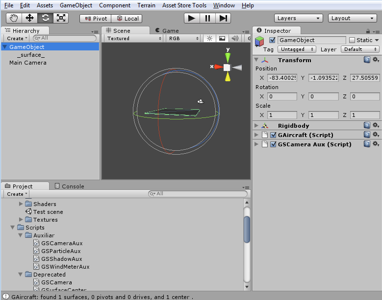
You can now test the package is working by adding a Cube GameObject with GameObject > Create other > Cube and then rename it to _surface_ (or instead of renaming attach a GSurface script) and place it inside the empty GameObject group with the GAircraft script attached. Finally scale the cube to Y 0.01.
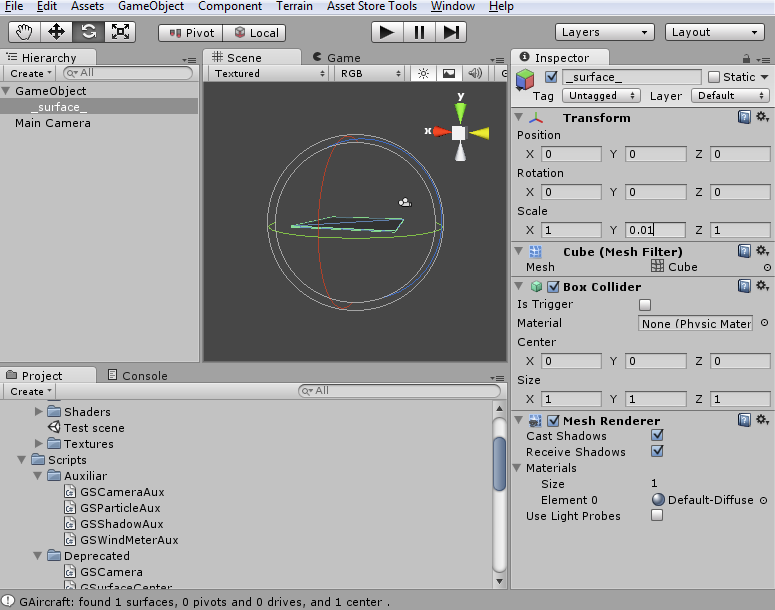
You can now run and you will see a growing vector that is the upwards drag force as the falling speed increases.
If you add a terrain and rotate slightly the GAircraft you will see how it flies down towards the direction you rotated it.
Tutorial Part 2: Adding control surfaces, mixings and engine (^ back to index)
Duplicate three times until you have four surfaces like the one used in the previous chapter..
Now, with four surfaces lets make them move with the cursors. For that purpose Pivots are used.
Pivots are rotating hinges. Each pivot rotates children around one of their axes: right, up or forward. Each pivot can mix up to three sources to get the rotation angle. If you need perform a rotation around more than one axis, you may put one pivot inside other pivot.

Put two empty groups inside the GAircraft group, in the (0, 0, 0) position and name it as left and right and the name of your chose. Then put the rear left surface inside the left pivot and the rear right surface inside the right pivot. Finally configure both pivots to rotate around the right axis and configure source 1 as elevator in both and set in both axis1min angle as -10 and axis2max angle as 10.
The axis min angle is the angle in which the pivot gets positioned when the input source is in the minimum value (usually 0) and the max angle is the angle in which the pivot gets positioned when input source gets its maximum value, usually 1. If more than one source are specified, all the angles are added.
Now add a second channel to both left and right pivots: set axis2 source as ailerons in both cases. In the right pivot set min angle to -10 and max angle to 10. In the left pivot set min angle to 10 and max angle to -10 (as you can see both angles are inverted, that is what we talked about just before, when ailerons source is 0, left pivot is 10 and right pivot is -10, when ailerons is 1, left pivot is -10 and right 10).
You may add a vertical stabilizer and a rudder, otherwise if you turn the airplane will strafe instead of turning. You can scale Y as 0.5 instead of Y 1.0 because rudder may affect less than the wings, set X as 0.01 and Z as 1. You can add a pivot to this new vertical surface and set axis1 source as rudder, pivot axis as up instead of right and you will get a rudder if you press Q or E.
Now the aircraft has h surfaces (wings, including ailerons/stabilizers) and v surfaces (v stabilizer and rudder). No friction are added by those surfaces with default settings. If you want to add some friction you may add an additional surface with scale X 0.1 Y 0.1 Z 0.01 in position (0, 0, 0). You can change the X and Y scales to increase the friction or reduce it.
You can change the center of mass by adding an empty GameObject and renaming it _center_. Moving the _center_ GameObject will affect the flying dynamics heavily, in next section there are some tips about this. You can also set the internal camera position by adding an empty GameObject and renaming it as _camera_.
Finally you can add a drive (engine) so fly is more stable (at low speed the surfaces does not get enough air flux to allow manoeuvre the airplane). Add a empty gameobject inside the GAircraft group and attach GDrive to it (or rename as _drive_) and set the force to ten times the weight of the airplane (set in the rigidbody GAircraft element).
Tips designing aircrafts (^ back to index)
Configuring global values (^ back to index)
GAircraft include some global values for ease (so it is not necessary to change then on each subelement of the aircraft.
The most important and used values are the switches for rendering surfaces, vectors and for enabling forces. For debugging the three must be enabled, and if you have any problem you can disable forces so the aircraft will behave like a normal Unity 3D Rigidbody (the GAircraft component will not apply forces except drives so no drag or lift forces are computed). There are lots of problems that happens without the surfaces forces working and have nothing to do with Aircraft Toolkit.
In release mode you may disable the rendering of surfaces (usually you have to add a visual model and you don't want to see the physic simulation surfaces) and you may disable also the vector rendering so no green / red / blue force vectors come visible. The vectors are useful to debug problems like instabilities.
Drag and Lift multipliers increase the efficiency of the surfaces. Debug nodes logs information about found nodes at the begin of the simulation and Wait frames are the number of fotograms that GAircraft wait at the beginning of the simulation until the library is enabled (this avoid startup instabilities and let the aircraft touch the ground without problems when execution starts).
Configuring inputs (^ back to index)
By default GAircraft comes configured to use Unity axis Horizontal and Vertical for ailerons and elevator but you can change anything in the Input properties, even disable input so automatic pilot or NPC controller can pilot the aircraft.
Every input channel is configured in the same way: the first element is to choose Source, you can choose between keys, unity axes or "user"/disable which disables the data management for this channel.
If you choose an exponential source type, then you can adjust exponential coefficient. If you choose to pick data from an Unity axis, you can write the axis name. If you choose use keys, you can select keys for increase channel from 0.5 to 1 or decrease channel from 0.5 to 0 (or on some channels the key works in toggle mode: each time pressed switches value from 0 to 1 or from 1 to 0), and in throttle channel you can choose afterburner which works as a parallel channel which overflows beyond 1 the value, how much is configured in each drive.
Finally if you choose keys you can adjust filters for making smoother the transition from 0 to 0.5 to 1, including the toggle channels (on this channels usually smooth filter is set to slower values).
There are some trimming and sensitivity values that usually allows ingame trimming and sensitivity adjustment.
Improving flying dynamics: Kinetics properties (^ back to index)
As you ended the previous tutorial you have got a flying airplane. However some flying dynamics can be improved.
The first thing you will realize if your aircraft is very light is that if you fly at high speeds it starts to vibrate. Some vibration is normal and it happens in the real world, but most of the vibration usually are related to the aliasing due digital physics simulation is performed in time samples (every nth second fractions) so sometimes the sampling frequency is not enough: when speed is too high. The effects are more visible when the aircraft is light because the small forces of the aliasing effects are more capable of make vibrations. To solve this issue you may use one or some of the antialiasing filter coefficients included in the GAircraft parameters.
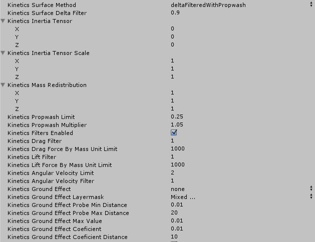
The most efficient is set Kinetics Surface Method to deltaFiltered or deltaFilteredWithPropwash and adjust Kinetics Surface Delta Filter. Default value is zero, increase it in steps of 0.1 up to 0.9 to remove the vibrations.
You can also adjust the Kinetics Drag Filter and Kinetics Lift Filter are also antialiasing filters. You must enable it by checking Kinetics Filters Enabled. You can set it at values between 0 and 1, usually at 0.5 to minimize the aliasing vibration effects.
Each one of these filters are used in a different stage of the simulation, so slightly different results in the dynamics are obtained. Depending of the Aircraft type sometimes one is best than the others, or maybe a combination of several different filters are the best.
Kinetics Drag and Lift Force By Mass Unit Limit also helps to control undesired effects. In this case this limit avoids excessive drag or lift forces are generated. In some cases like impacts or sudden speed changes, excessive speeds... a overflow in the forces can be generated. Usually this heads in the real world to the destruction of the aircraft. In the simulation however this generates a excessive force that can be detected but if not stopped the simulation can head to a unstable status. Usually a value of 1000 or 10000 units in those filters help to limit the overflow. Lower values makes the drag and lift forces are lower than required to make realistic turns.
Kinetics Propwash properties improve flight dynamics on light acrobatic aircrafts. Sometimes you can see videos where the pilots makes the aircraft to make turns on very low speeds, even completely stopped in the middle of the air. Most airplanes controls (ailerons, elevators, rudder) works because of the air flux travelling between them. When aircraft is stopped or flies slow not enough airspeed is generated. How those acrobatic pilots can do such things then? The answer is that the propellers generate enough wind backwards to get alive the controls even in stop condition. The Propwash simulation simulates those airwash generated by oversized propellers present in some acrobatic aircrafts.
Inertia tensor can be also adjusted in the Kinetics properties. Usually Unity3D calculates the inertia tensor, but sometimes this calculated tensor can be not enough accurate for some reason (maybe some aircraft parts are too light). Anyway if you realize that your aircraft resists to make turns around one of the axes, adjust the Kinetics tensor scale or the weight redistribution. For example most airplanes wings are lighter than calculated by Unity, in that case you must change Kinetics Mass Redistribution X value to something between 0 and 1 (wings are placed in the X axis). The more near zero, the more efficient your airplane's ailerons will be (turns around Z axis), but also the rudder (turns around the Y axis). If for some reason you want only the turns around the Z axis are enhanced, change the Tensor Z scale to a lower value instead of changing the mass redistribution. Both values (tensor scale and tensor mass redistribution) can be used and adjusted at once. Those values will affect the Unity3D calculated values.
Finally the Ground Effect. This effect makes that wings or rotors near the ground are This properties are still beta but can be used in helicopters. Them need that the terrain and other surfaces that causes ground effect are attached the the correct layer and the ground effect layermask are correctly set. Even then please test the ground effect
Surfaces, how to place it, how to design a aircraft from blueprints (^ back to index)
Aircraft Toolkit works calculating the forces that affect one surface.
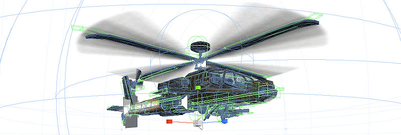
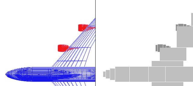
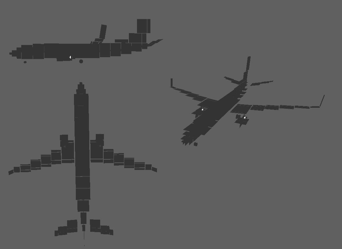
But how does those ugly squared plates are able to work and calculate a reliable physics model? (that of course you can hide after physics model is tested ;) Default Aircraft Toolkit surface configuration makes each surface react only to parallel fluxes to the less wider dimension axis. This implies each surface is a blade with the default configuration. We use Cube GameObjects and we scale one of the dimensions to a little value. This in conjunction with the fact of forces works incredible well with vector projections and compounds, so you can model any volumetric body by using 3 or more surface planes, each one not parallel to each other; usually we use surfaces perpendicular to each one of the axes: front, side and top, but you can rotate them to an arbitrary angle in groups or individually. The most important is to respect the apparent surface area in each direction (with is ~1.1 for cubic and cylinder shapes, ~0.8 if lengthy, ~0.5 for spheric and conic shapes, 0.05-0.1 if lengthy and peak ended (usually wing sections or perfect bodies like Sears-Hack shape). Now, due most airplanes have two type of shapes: conic or spheric in the side and top flux sections, so we can assume full area and a correction of 0.4-0.5 cd global shape coefficient (we use the global drag and global lift multiplier coefficients for change this), and for the front-to-rear axis most aircrafts are lengthy stylized shapes, so much less drag usually with cd of 0.05 to 0.1 and usually the symmetric shapes which helps to integrate every single element into a global small drag surface parallel to the front plane. Wings top-down profile depending on the shape can be from 0.8 to 2.0 cd.
So that explains how the examples work: squared airplates trying to respect the local area on the side and top blueprint planes and a single small plate parallel to the front plane (the drag plate), and depending on the aircraft shapes a value of 4 or 5 in the global multiplier in the GAircraft component.
The drag plate can be sized by running the simulation and setting the engine to the cruise %, at the cruise height at the cruise speed and resizing the drag plate until the cruise speed is approximately stable.
Pivots and channels, and trimming (^ back to index)
As saw in the adding control surfaces and mixings, pivots are maybe the second most important elements of the aircraft.
Once you have the blueprints and you have rotated the wings to respect the attack angles, and the wheels are in place, you may place the center of mass.
The center of mass first positioning limit comes from the wheels: place it too much far from recommended point will make the aircraft rise one or more of the wheels from the ground.
Usually the center of mass is a little after the main wings, or at least near the main wings (the wheels positions usually helps also to identify it). On some aircrafts center of mass can be moved without problem and flight will remain stable, on others a little change will make the aircraft bank.
Once the center of mass is placed, it comes the last step: you may trim the elevator until the aircraft is stable at cruise speed.
Now, how to do all these: the first is to add pivots.
To add a pivot you add a empty GameObject inside the GAircraft group. Then you can attach GPivot script or rename it to _pivot_. It is faster and more light to use _pivot_ renaming, but no problem if you use for pivots the GPivot script. Select around which axis will rotate the pivot. You can place the pivot GameObject inside other elements and rotate parents. Remember the pivot rotating axis is local. You can see local axes by adjusting pivot-local in the toolbar of Unity 3D. The red axis is right, the blue is forward and the green is up.

You can rotate parent to modify then the pivots rotation without problem. If you rotate the pivot itself, maybe you will need to adjust then the Rotation around Forward/Right/Up Offset values depending on the version of Aircraft Toolkit that you use.
Finally comes the adjustment of the source channels for the rotation: you can set up to three channels: you can make for example to rotate on elevator, ailerons and on flaps values. In the practice more than three channels can be added because each pivot has an Id and you can use one pivot Id as a channel too in other pivot. This allows pivot and channel arithmetic without effort. Remember altitude, accelerations and gear positions are also available, avionic controllers also add channels... and you can use pivots not only for control surfaces: also for engines, rotors, gears, cockpit controls and gauges so this setup allows you to control every single aircraft part easily.
Even a bird's wing can be controlled by pivots.
Camera Tweaking (^ back to index)
Section being wrote.
Tips designing helicopters (^ back to index)
Using rotor and tailrotor drives (^ back to index)
Instead of using classic drives, for helicopters you may use rotor and tailrotor drives when variable pitch rotors may be simulated. To enable a drive as a rotor use the type parameter.
The rotor drive type allows not only configure one channel for collective, but also other two input channels for cyclic. You can even use a Pivot output as input channel.
To place the rotor or the tailrotor, please do not rotate the drive. The rotor type generate the lift upwards, in the direction of the green arrow, and the tail rotor generates lift in the right axis, the red one.
Rotor simulation is performed using the blade parameters, so please configure the number of blades and its geometry. In next release the simulation will include also embedded virtual surfaces (now you may place four surfaces in the rotor) and momentum. For now the gyroscopic effect is included.
Tailrotor allows you to use it like a rudder.
You may add avionics controller for stabilization in future releases because a helicopter without stabilization is very influenced by winds.
You can use various rotors, for example in a Chinook. Simply place two rotors and it will work. However rotors may not be used always. For example, if you have a quadrotor, usually those aircrafts use fixed pitch rotors. Those rotors may be simulated by a normal propeller drive. You can use variable pitch rotors like an helicopter, but remember in the real world most quadcopters does not use variable pitch.
For multirotors you can use Pivot aricmetic for control the collective/power of the different rotors.
Understanding classes and properties (^ back to index)
Aircraft parameters (GAircraft) (^ back to index)
GAircraft is the main class. Each aircraft needs its parent object to include one reference to this class (or it's deprecated name GSurfaceManager).
This class has lots of properties, but most of them are only used to tune fine physics properties and will be ok with its default values. The more important is to understand each group of properties, what solutions offer and whichone should be changed to get your desired behaviour.
Currently there are 5 groups: global, input, kinetics, gauges and crash.
Global properties group (^ back to index)
The global group controls values that propagate to every children element of the aircraft. For example if you modify the drag multiplier, this will affect every surface under this aircraft, or if you enable or disable one of the rendering flags, this will affect every children.
- Global Drag Multiplier: is the global airplane drag constant. Usually it is set to 10.0f, you may not change it unless your model does not fly as you spect. Higher values will make air fluid more dense. You can also adjust separately for each surface.
- Global Lift Multiplier: is the global airplane lift constant. You may change it if your plane does not respond as spected. Higher values will increment lift force. You can also adjust separately for each surface.
- Global Render Physic Surfaces: if not marked, the physic model surfaces will be invisible without needing to disable it one by one. GSurfaceManager will do it for you. This is the recommended form.
- Global Render Force Vectors: if marked you will see the force vectors that operates over each one of the surfaces.
- Global Apply Force Vectors: if unmarked, the fight physics will be disabled so no drag or lift forces will be applied. This is useful to test if your model works ok.
- Global Wait Frames: on some models a short lapse without applying forces is good to avoid instabilities due to initialization.
Input properties group (^ back to index)
The input group allows you to preset which Unity axes will affect each one of the channels. You can change the input mode to accept keys, to use the unity inputmanager system or to listen your own values. You can switch channels behaviour between exponential, linear or inverted and you can adjust smoothing and resistance values.
The input group is subdivided into some common properties and each one of the channels' groups, currently: elevator, ailerons, rudder, throttle, gears, flaps, brakes and smoke trails.
Common input properties
- Input Trim Step: Is the value in which the trim setting changes when the key combination is pressed.
- Input Trim Max: Is the max value of trimming allowed.
- Input Trim Min: Is the min value of trimming allowed.
- Input Trim Key: Is the key which in combination with the input channels keys will change the trim value.
- Input Sensivity: Is the sensitivity of the inputs. For some aircraft change this may change acrobatic mode and flight mode.
- Input Sensivity Step: Is the step value in which the sensitivity changes.
- Input Sensivity Min: The minimum allowed sensitivity.
- Input Sensivity Max: the maximum allowed sensitivity.
- Input Sensivity Key for Increment: The key for increment sensitivity.
- Input Sensivity Key for Decrement: the key for decrement sensitivity.
- Input Sensivity Coefficient Speed: the coefficient that changes sensitivity, the most speed, the less sensitivity.
- Input Sensivity Coefficient Speed Limit: the limit to the coefficient variation.
Channel properties
After the common properties comes each one of the channels' groups, currently: elevator, ailerons, rudder, throttle, gears, flaps, brakes and smoke trails. Each one of the channels have approximattely the same properties (where [Channelname] is the channels' name):
- Input [Channelname] Source: selects the source of the axis data: you can choose between keys and unity axes with various presets (inverse, exponential...), or choose user (does not write over [Axisname]_output variable and the user application should do manually.
- Input [Channelname] Source Exp K: write the coefficient for exponential curves: 1 is linear, the bigger the number, the most exponential the curve is.
- Input [Channelname] Source Unity Axis: you can write here the name of the unity axis as configured in the Input Manager, only if you marked as _source the options unity_axis or inv_unity_axis.
- Input [Channelname] Key For Increment: if you choose keys in Source, this key will increase the value to the maximum while is pressed.
- Input [Channelname] Key For Decrement: if you choose keys in Source, this key will decrease the value to the minimum while is pressed.
- Input [Channelname] Key For Afterburner: in this case the value will be increased beyond the maximum, to the afterburner setting while is pressed.
- Input [Channelname] Key For Toggle: in this case the value will be toggled between minimum or maximum each time the key is pressed if the last toggle finished.
- Input [Channelname] Key Smooth Filter: slows down the response until it is realistic, only with keys or keys_exp. Use values between 0.0 and 1.0. You usually should use values near 0.1, 0.01 or 0.001.
- Input [Channelname] Trim: is the trim value for this input channel.
Kinetics properties group (^ back to index)
- Kinetics Inertia Tensor: you can manually adjust the inertia tensor, or left to zero and will be autocalculated using following values also:
- Kinetics Inertia Tensor Scale: if you left the inertia tensor to zero, this scale will affect the autocalculated tensor scaling it.
- Kinetics Mass Redistribution: similar to Tensor scale, but easier to use this affect the tensor if it had been autocalculated. In this case mass redistribution reorganizes mass in the proportions indicated, for example if you want to reorganize the weight far from the tail and the front of the plane, decrease the Z component to a value lower than 1, if you want to make the wings lighter, adjust X to a lower value.
- Kinetics Surface Delta Filter: this affect to the surface speed calculation; with 0 no filter will be applied, with 1 no changes in position will be detected. You can use this value to avoid oscillations in some airplane shapes: test values. For example strange values like -0.1 can avoid oscillations and acts like a avionics controller on some cases.
- Kinetics Propwash Limit: this value affects to the force applied by propwash: the surfaces near the propeller have far more wash effect, this value reduces the different between surfaces near the propeller and the rest of the plane.
- Kinetics Propwash Multiplier: this multiplies the wash effect. Usually maybe 1.
- Kinetics Filters Enabled: this affects the following filters:
- Kinetics Drag Force By Mass Unit Limit: limits the forces by mass unit: reduce to 10 or even less this value if your plane starts fast vibration, until the vibration stops. Warning: if you reduce this value too far the airplane will not fly, check the new values.
- Kinetics Lift Force By Mass Unit Limit: same like before, but for lift forces. Take into account that some lift forces are in fact drag forces, so use this two values paired is a good practice, but you can try to increase or decrease this value independently.
- Kinetics Angular Velocity Limit: unity physics engine sometimes makes unrealistic spins: for this cases use this value to limit the maximum angular velocity.
- Kinetics Angular Velocity Filter: this affects to the angular velocity variation making it smoother near 0, and unfiltered when 1.
Gauges properties group (^ back to index)
- Gauges Altimeter Generate: enable if you want to use the altimeter pivot in your geometry.
- Gauges Vario Generate: enable if you want to use the variometer pivot in your geometry.
- Gauges Rpm Generate: enable if you want to use the tacometer pivot in your geometry.
- Gauges Airspeed Generate: enable if you want to use the velocimeter pivot in your geometry.
- Gauges Heading Generate: enable if you want to use the compass pivot in your geometry.
- Gauges Gs Generate: enable if you want to use the vertical acceleration meter pivot in your geometry.
Crash properties group (^ back to index)
Now the winds and the shadows management had been moved to other objects. Wind is now calculated by GSurfaceWindZone, and can be obtainer by GSurfaceWindZone.windAt(position). Shadows are now processed by GSShadowAux: you'll need to attach them.
Surface parameters (GSurface or tag name _surface_) (^ back to index)
- Surface Enable: allows to disable the surface for debug purposes.
- Surface Enable Thin: enables the filter that uses only the thinnest side-to-side perpendicular surfaces and avoids the other. You may let this value to marked.
- Surface Enable Positive: if disabled forces generated by velocities from negative side to positive side of the surface are ignored. You may let this value to marked.
- Surface Enable Negative: if disabled forces generated by velocities from positive side to negative of the surface side are ignored. You may let this value to marked.
- Surface Enable XPositive or YPositive or ZPositive or XNegative or YNegative or ZNegative: these properties are exactly the same than the two precedent, but only for X, Y or Z components. You may let these values to unmarked (if the two precedent were marked).
- Coefficient XDrag or YDrag or ZDrag: the coefficient of drag in the components, usually let these values to 1.
- Coefficient X/Y/ZLift When X/Y/ZPositive or X/Y/ZNegative Flow: these values affect the lift forces when airflow travels in X/Y/Z components to positive or negative sides. Usually all these values are 0 except of Coefficient YLift When ZNegative Flow which is the flow from front to back of the plane and of the wing shape.
- _nolift_: lets all lift coefficients to zero.
- _hide_: makes the surface not visible in the box rendering model.
Center parameters (GCenter or tag name _center_) (^ back to index)
Has no parameters. Toolkit uses it as a mark for the rigidbody center of mass.
Camera parameters (_camera_ tagname only) (^ back to index)
Has no parameters. Toolkit uses it as a mark for the internal camera position.
Drive parameters (GDrive or tag name _drive_) (^ back to index)
- Type: the drive type. basic is a basic drive that generates force, no propeller or other effects will be simulated. propeller simulates propellers, including propwash. turbofan is not yet implemented. other values are not yet implemented.
- Powered: marked if this engine is working, otherwise will not be processed.
- Power Control By / Power Control By Pivot: determines the collective or main power control axis.
- Power Cyclic Forward Control By / Power Cyclic Forward Control By Pivot: the same, but controls the cyclic-forward.
- Power Cyclic Side Control By / Power Cyclic Side Control By Pivot: the same, but controls the cyclic-side.
- Throttle Reverse: On some planes allow the plane to go backwards.
- Throttle Idle: the throttle value when in minimum value. Usually should be 0.
- Throttle Max: the throttle value when in maximum value. Usually should be 1 or the newtons dryforce generated by the drive.
- Throttle Afterburner: the throttle value when in afterburner value. Usually should be greater than 1 and less or equal than 2, or the afterburner force in newtons generated by the drive.
- Throttle Rpm Conversion Ratio: this ratio is multiplied to Throttle value to get the rpms of this engine shaft.
- Throttle Rpm Conversion Filter: the conversion can be filtered so the rpms will change a little slower than instantaneous making more real the motion.
- Mass: the mass of the rotor, will be used for kinetics calculations.
- Blade Number: if the shaft have propeller blades and you want to simulate propeller, write how many blades there are.
- Blade Length: the length from the shaft to the extremum, this is usually the longest dimension.
- Blade Width Min: the minimum width, usually is the width near the shaft.
- Blade Width Max: the maximum width, usually is the width near the extremum.
- Blade Angle Yaw: is the angle around the axis between the shaft and the extremum. The more yaw it is, the more propulsion the propeller generates.
- Blade Angle Pitch: is the angle from the perpendicular plane to the shaft.
- Blade Shape Coefficient: similar to the coefficient found in surfaces.
- Blade Wash Enabled: enables additional airspeed generated by the propeller; this allows the plane to turn even at zero speed with no winds. Usually is used in acrobatics.
- Blade Wash Radius Normal: the wash radius from the shaft.
- Blade Wash Radius Tangent: the wash radius from the propeller position to the tail.
- Blade Wash Factor: this is the factor of wash generation: the bigger, the more wash is generated.
- Rotor Collective Bias: Is the position of the blades in case of no input channel value.
- Rotor Collective Coefficient: The amount of displacement when the input channel associated to collective changes.
- Rotor Cyclic Forward Coefficient: The amount of displacement when the input channel associated to cyclic forward changes.
- Rotor Cyclic Side Coefficient: The amount of displacement when the input channel associated to cyclic side changes.
- Rotor Autorotation Coefficient: This coefficient determines the behaviour in case of sudden power loss, and the rpms loss in case of collective holds high too long.
- Shaft Output Pivot Id: this is the pivot name were the shaft angle will be stored.
- _force:N_ the force for dry and aft.
- _dryforce:N_ the engine_dry_force value.
- _aftforce:N_ the engine_aft_force value.
Pivot parameters (GPivot or tag name _pivot_) (^ back to index)
- Rotation Pivot Axis: is the axis around which the pivot rotates. Usually right for elevator and ailerons and up for rudder.
- Rotation Around Forward Offset: is the pivot rotation offset around the forward axis.
- Rotation Around Right Offset: is the pivot rotation offset around the right axis.
- Rotation Around Up Offset: is the pivot rotation offset around the up axis.
- Ch NSource: the Nth source of rotation. There can be up to three sources, added to the angle of rotation around axis_rotation. If you need to rotate between two or more axis, use two or more pivots.
- Ch NSourceName: if your source does not appear here, mark the source as any and write here the name manually.
- Ch NPivot Angle When Min: this is the minimum angle when value is 0.
- Ch NPivot Angle When Max: this is the maximum angle when value is 1.
- Ch NPivot Turns Per Unit: this value is the amount of turns per input unit. For example in an altimeter a value of 1 will make the gauge to make a 360º turn when plane ascends 1 meter.
- _right_ _forward_ or _up_ marks the axis_rotation axis.
- You can also use _pivotforward_ _pivotright_ or _pivotup_ instead of _pivot_ to specify the axis_rotation axis.
- _rightoffset:N_ _forwardoffset:N_ _upoffset:N_ specifies the axis_*_offset values.
- _axis*:S_ specifies the axis*_source value, where * is 1/2/3 and S can be none/elevator/ailerons/rudder/gearsdown/flapsdown/brakes/engine/throttle/altimeter/vario/rpm/velocity/heading/gs
- _axis*min:N_ the axis*_min_angle value.
- _axis*max:N_ the axis*_max_angle value.
- _axis*mul:N_ the axis*_mul_angle value.
For example, your pivots name can be yourname_pivot_up_axis1:rudder_axis1min:-32.5_axis1max:32.5_
WindBasic parameters (GWindBasic) (^ back to index)
Attach this to an empty gameobject or to a windzone gameobject.- Bias Speed: is the continuous speed in m/s of the wind, towards the forward direction of the gameobject.
- Gust N Speed: the speed for this gust.
- Gust N Frequency: is the wind gust frequency: 0.1f means each 10 seconds a peak of this gust will be reached.
Trail parameters (GTrail) (^ back to index)
Can generate a trail from the position where the object is.- Surface Id: the id of the surface where this trail is associated.
- startsWidth and endsWidth: put your desired values, usually 0.1f and 4.1f or greater.
- startColor and endColor: includes your colors.
- Material Name: the material to use with object name.
- forceThreshold: unused in this version.
- speedThreshold: unused in this version.
LandingGear parameters (GLandingGear) (^ back to index)
You must attach this script to every wheel on the aircraft to avoid friction issues because Unity's wheels are for use on cars, not airplanes.- brakeForce: The amount of brakeforce to apply when brake input is enabled: usually must be around 1000, but on some light aircrafts 250~500 can be enough.
- frictionExponentBaseCoefficient and frictionExponentDivisorCoefficient: controls how much the friction must decay with the speed. This values must be configured depending on the aircraft weight: the less weight the more lift and the less friction the wheels may perform to get real behaviours.
Auxiliary scripts (^ back to index)
There are three auxiliary scripts: GSCamera, GSWheelAux and GSWindMeterAux.- GSCameraAux should be attached to the root/rigidbody/GSurfaceManager gameobject and will control the camera and sound for the simulation. You can use your replacement easily.
- GSParticleAux controls particle emission.
- GSShadowAux attach this to a object and a shadow will be generated by raytrace from the tagged object to the floor. Can be attached to any part, but usually it is added to the GAircraft and the wheels.
- GSWindMeterAux controls a windmeter that is included in the sample scene.
Frequent answered questions (^ back to index)
My airplane starts to vibrate when it reaches some speed. What is happening? How can I solve it?
This issue happens because of the physics sampling rate when speed-weight ratio is too high. In each physics frame the tail (or other body part) is affected by a force which adds enought speed so in the next frame the process repeats but in the contrary direction. This is the same issue that happens with sample sounds or images: the aliasing.
To solve this situation you can perform one or several actions: You can use one of the kinetics filters so it act as anti-aliasing filter, you can increase weight or you can add a drag surface to the aircraft so it never will reach such a speed.
The helicopter flies out of control. What can I do?
Helicopters are unstable by nature. In fact if you review the history of helicopters they didn't fly quite well until some elements where introduced. In our case we need to introduce stabilizers simulation so flight can be a bit controllable.
In the next release (0.78) we will include a new kind of rotor component "basicrotor" to use instead of the current rotor+tailrotor components meanwhile we didn't concluded the stabilizers development. You can test this new rotor component on the following webplayer: http://gargore.com/uas/aircraft-toolkit/demo.0.78.2.php